PHASE 1 · HARDWARE BRING-UP · ACTIVE

Daedalus

A custom rocket flight computer built from the board up — scratch-written embedded firmware on a Teensy 4.1, designed to be validated through a software- and hardware-in-the-loop test pipeline before it ever leaves the pad.

Daedalus rocket emblem
EMBLEM · REV 1AVIONICS / GNC
600 MHz
Cortex-M7 flight CPU
9-DoF
Inertial sensing
100%
Firmware from scratch
SITL+HITL
Test pipeline
Overview

An avionics stack engineered the way flight hardware should be.

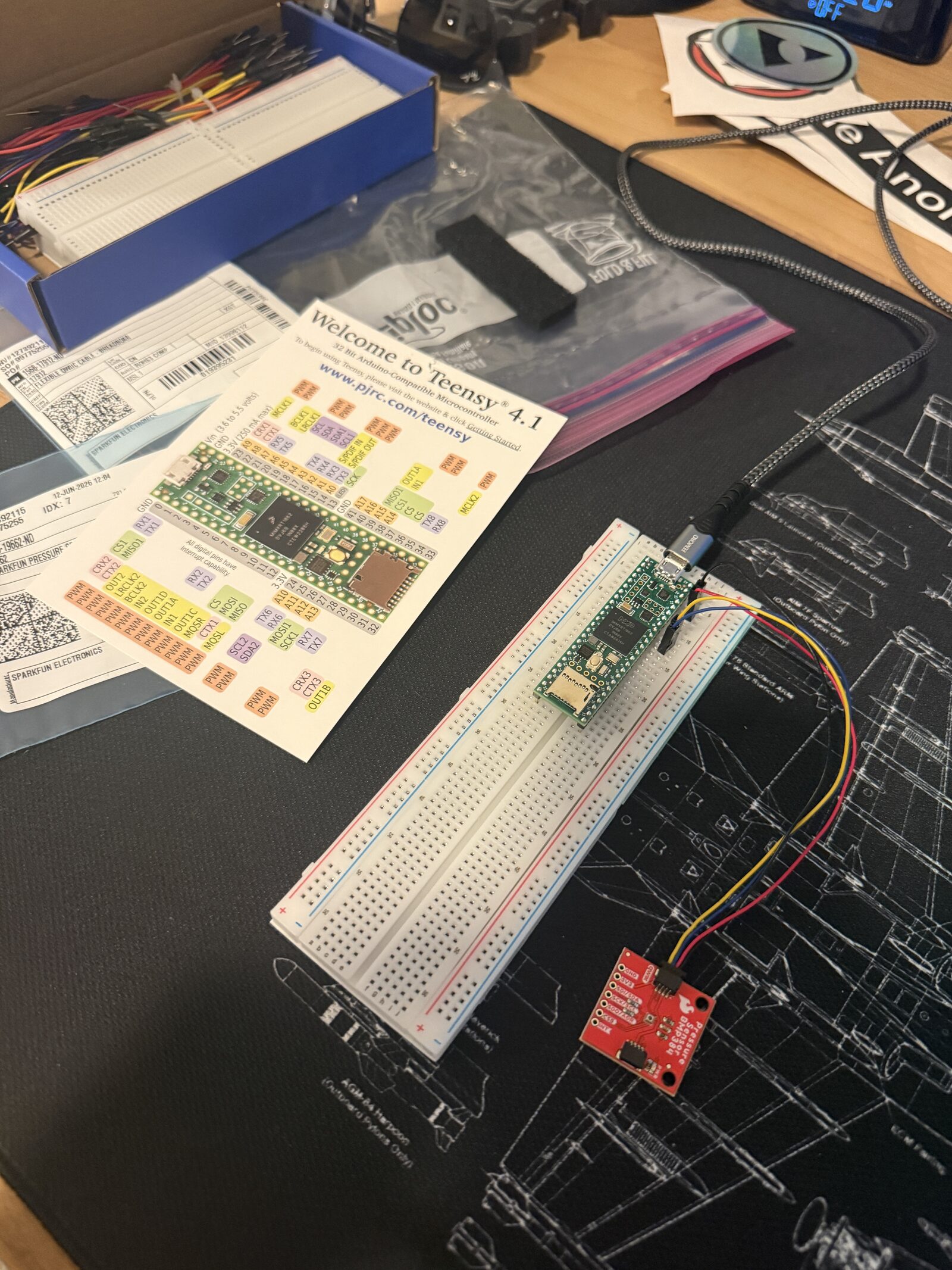
Daedalus is a personal R&D project to design, build, and qualify a rocket flight computer end-to-end — the printed circuit, the sensor suite, the embedded flight software, and the test infrastructure that proves it works. The goal isn't just a board that boots; it's a system whose behavior is verified in simulation and on the bench before any real flight.

Philosophy

Test-driven flight code

Every guidance, navigation & control path is exercised in a simulated environment first, so the firmware that flies is the firmware that's already been proven against thousands of synthetic trajectories.

Scope

Full-stack, board to launch

Sensor drivers, state estimation, flight state machine, data logging, and a ground-test harness — all written from scratch in C++ on bare-metal Teensy, with no flight-controller framework underneath.

Current state

Where the project stands today

Daedalus is in Phase 1 — hardware bring-up. The core compute and the barometric sensor are alive on the bench; the next milestones build the full sensor suite and the simulation harness around it.

In progress

Phase 1 — Hardware bring-up

Teensy 4.1 running on the breadboard with a BMP384 barometric pressure sensor wired over I²C. Validating clocks, power, bus communication, and clean sensor reads as the foundation for everything above it.

Next

Phase 2 — Full sensor suite & state estimation

Integrate the ICM-20948 IMU and NEO-M9N GPS, then fuse barometric altitude, inertial, and position data into a real-time state estimator for attitude and altitude.

Planned

Phase 3 — SITL / HITL test pipeline

Stand up software-in-the-loop simulation of full flights, then hardware-in-the-loop replay on the real board to catch timing and integration faults the simulator can't.

Planned

Phase 4 — Ground test & first flight

Custom PCB, vibration and power-cycle bench testing, static rehearsals, and a maiden flight with full telemetry capture for post-flight reconstruction.

Hardware

The flight stack

A compact, high-rate avionics package chosen for deterministic timing and proven aerospace-grade sensing.

Compute

Teensy 4.1

600 MHz ARM Cortex-M7 — the brain running the bare-metal flight firmware.

MCU · IMXRT1062
Inertial

ICM-20948

9-DoF IMU: 3-axis gyro, accelerometer & magnetometer for attitude.

9-DoF · SPI/I²C
Barometric

BMP384

High-resolution pressure sensor for altitude and apogee detection.

BARO · I²C
Position

NEO-M9N

Multi-band GNSS receiver for ground-truth position and recovery.

GPS · u-blox
From the bench

Phase 1, captured

Teensy 4.1 on a breadboard with a BMP384 barometric sensor connected over jumper wires, on a blueprint mat
FIG. 01 — FIRST POWER-ONBREADBOARD · I²C

First light on the bench

The very first Daedalus build: a Teensy 4.1 and a BMP384 barometric sensor talking over I²C, wired up on a breadboard atop a blueprint mat. Not glamorous — but this is where every flight computer earns its trust, one clean sensor read at a time.

  • ATeensy 4.1 — the 600 MHz flight CPU, powered and enumerating its peripherals.
  • BBMP384 barometer — pressure sensor on the SparkFun breakout, returning live altitude data.
  • CI²C link — jumper-wired bus carrying sensor traffic to the MCU for validation.
Software & validation

Firmware that's proven before it flies

The flight software is written from scratch in C++ and validated through a layered test pipeline — so failures surface on a laptop or a bench, never at apogee.

01 · MODEL
Flight simulation

Synthetic trajectories & sensor data drive the firmware through full mission profiles.

02 · SITL
Software-in-the-loop

The exact flight code runs against the simulator — logic verified end-to-end.

03 · HITL
Hardware-in-the-loop

Real board, simulated world — catches timing & integration faults pre-flight.

04 · FLIGHT
Live flight + telemetry

On-board logging captures every state for post-flight reconstruction.

On-board

Bare-metal flight firmware

Sensor drivers, a deterministic main loop, a flight state machine (boot → armed → boost → coast → apogee → descent → recovery), and high-rate data logging — written directly against the hardware in C++.

Ground

Test & analysis harness

Tooling to drive simulations, replay recorded flights, and visualize estimator output — turning every run into data that hardens the next iteration.