Next-generation carrier-based strike fighter designed to replace the F/A-18E/F Super Hornet — with twin F119 afterburning turbofans, internal weapons carriage, and advanced survivability for the 2035 carrier air wing.
Aircraft Overview
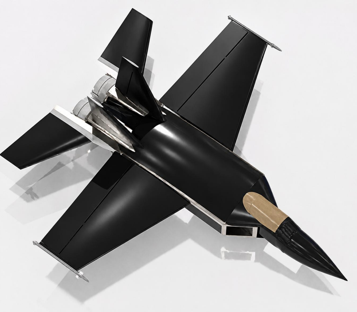
The F-44 Falcon is a twin-engine, carrier-based multirole strike fighter developed by Team ALEBORNE at San Diego State University in response to the 2025–2026 AIAA (American Institute of Aeronautics and Astronautics) Navy Request for Proposal. It is designed to replace the F/A-18E/F Super Hornet while remaining compatible with CVN-68 and CVN-78 class aircraft carriers.
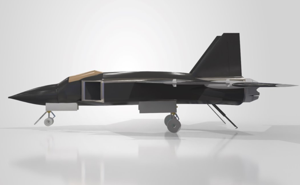
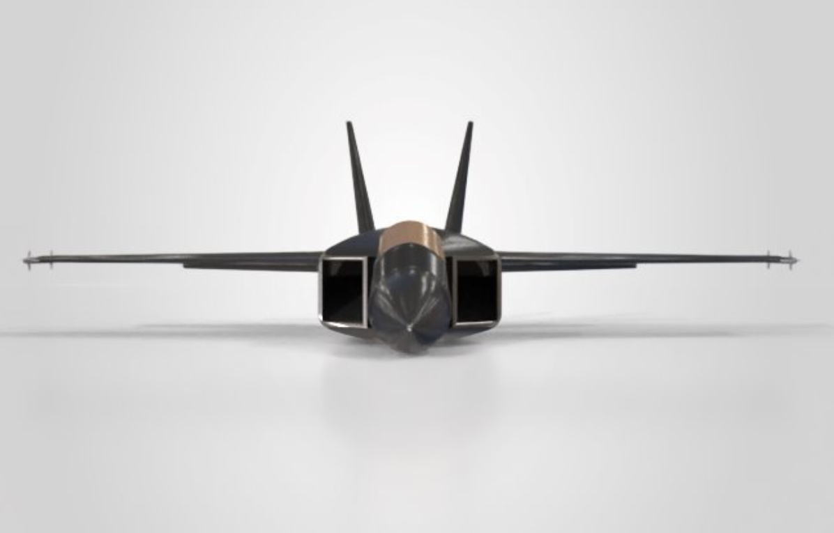
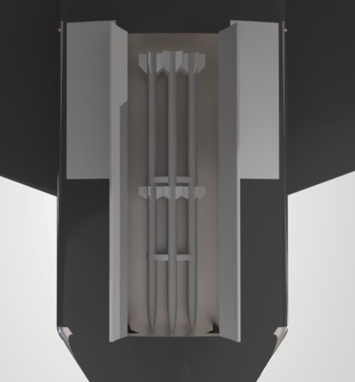
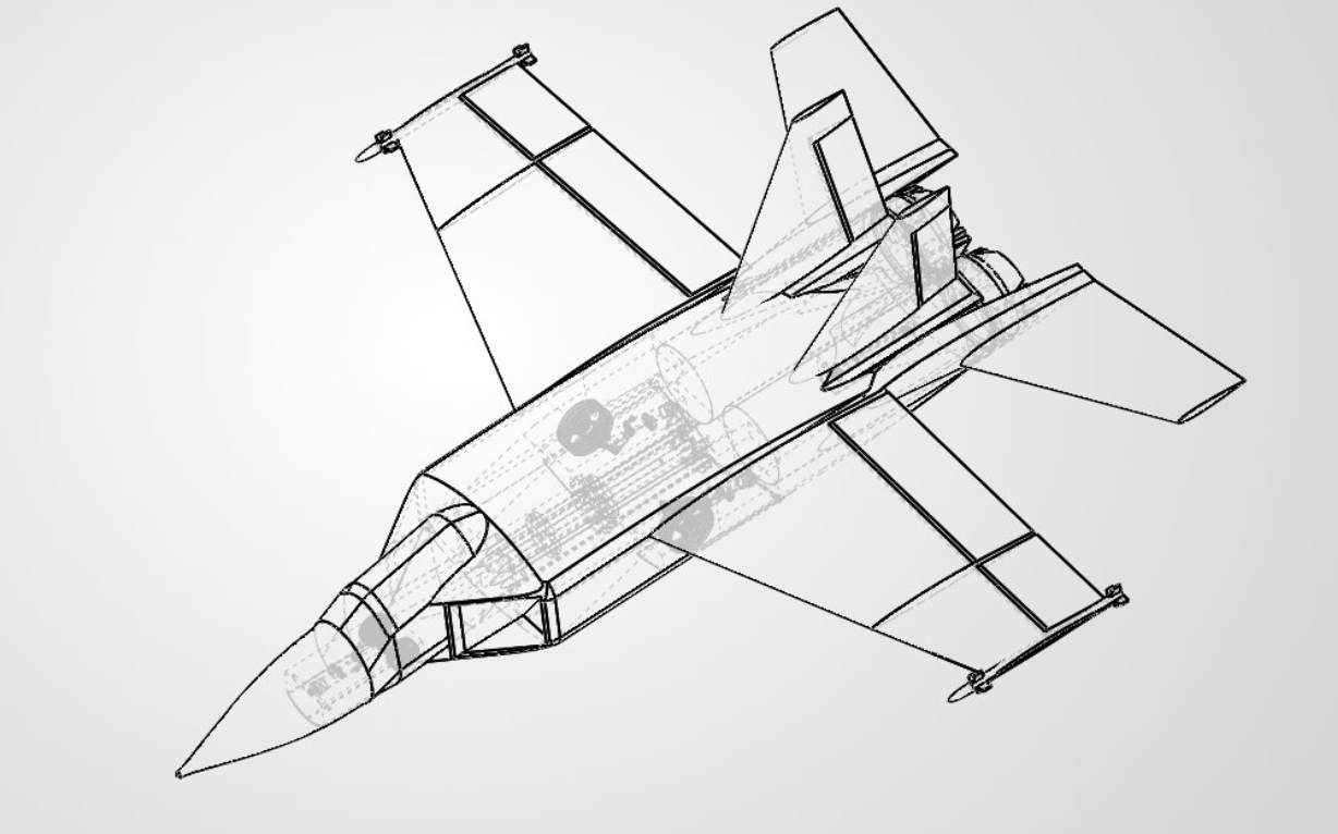
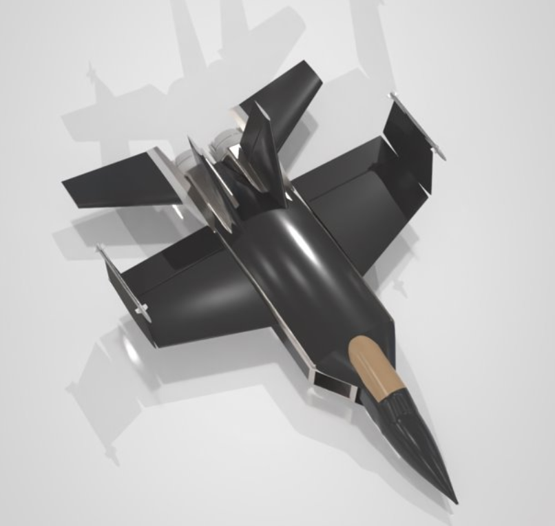
Inspired by the F-14 Tomcat, F/A-18E/F Super Hornet, and F-35C Lightning II, the F-44 incorporates an internal weapons bay for reduced RCS (Radar Cross-Section), a swept-wing planform with twin vertical tails, twin F119-PW-100 afterburning turbofan engines, folding-wing provisions, reinforced landing gear, a nose launch bar, and an arresting hook.
The design philosophy prioritizes proven subsystems (TRL 6+ — Technology Readiness Level), production-available materials suitable for a 25-year maritime service life, and cost-conscious technical maturity to support a practical 2035 IOC (Initial Operational Capability).
The People Behind It
Seven aerospace engineering students at San Diego State University, collaborating across all aircraft design disciplines.
Design Evolution
The F-44 evolved through multiple design iterations — from preliminary weight estimates and 2D sketches, through wing layout trade studies, to a finalized CAD model reflecting carrier-compatible geometry and internal payload integration.
Wing Design: The main wing features a 457 ft² planform area with a 45 ft unfolded span (35 ft folded for carrier storage), a sweep angle of 20°, taper ratio of 0.5, and an aspect ratio of 4.43. Trailing-edge flaps retract at 25% chord with 80% wing coverage and a maximum deflection of 40°.
Airfoil Selection: A dual-airfoil approach uses the NACA 65-412 at the root and NACA 65-206 at the tip, selected through a trade study balancing subsonic CL/CD (Coefficient of Lift to Coefficient of Drag), transonic performance, and supersonic efficiency. The 6% double-wedge profile was identified for maximum L/D at supersonic cruise.
Empennage: Twin vertical stabilizers (100 ft² each, 16 ft height, 46° LE sweep) provide directional stability. An all-moving horizontal stabilizer (110 ft², 19 ft span, 29° LE sweep, AR 3.28) delivers high pitch authority for maneuvering, trim, and carrier approach. Horizontal tail volume coefficient is 0.4133; vertical tail volume coefficient is 0.0766.
Technical Specifications
Key performance parameters and geometric characteristics from the F-44 Critical Design Review (CDR).
Propulsion
The F119-PW-100 was selected through a formal engine trade study against the F404 and F414 families. The F119 provides substantially higher thrust, enabling the acceleration, climb, and sustained combat performance required by the AIAA RFP (Request for Proposal).
Each engine produces 26,000 lbf dry thrust and 35,000 lbf in afterburner, with a TSFC (Thrust-Specific Fuel Consumption) of 0.8/1.7 lb/lbf·hr (dry/AB), a bypass ratio of 0.30:1, an overall pressure ratio of 26:1, and an airflow of 250 lb/sec. Each engine weighs approximately 5,000 lb.
Rectangular inlet ducts (1,059 in² capture area) are mounted slightly off the fuselage to ensure high-momentum freestream air reaches the engine intake. The actual duct is 1.53× the minimum required area, providing margin for high-AoA (Angle of Attack) operation and future growth. Convergent-divergent afterburning nozzles maximize high-temperature exhaust flow.
Structures & Loads
The wing structure is designed for a limit load factor of 7.5g with a safety factor of 1.5, giving an ultimate load factor of 11.25g per MIL-A-8861B. At ultimate loading, the wing sustains up to 20,250 lb/ft of spanwise load distribution, 358,000 lb of shear, and 3,416,000 lb-ft of bending moment.
Wing box construction: Spar thickness of 0.52 in, spar cap thickness of 0.50 in, rib thickness of 3.397 in, and stringer cross-section of 0.75 × 0.75 in². FEA (Finite Element Analysis) was conducted using Aluminum 7075-T6 with zinc coating for corrosion resistance in the maritime environment.
The V-n diagram confirms the aircraft is maneuver-critical: gust loads at all evaluated speeds remain well below the structural limit. Maneuvering speed VA = 764 ft/s EAS (Equivalent Airspeed), with VC = 903 ft/s EAS and VD = 1,362 ft/s EAS.
Interactive 3D Model
Rotate, zoom, and inspect the full CAD geometry. Click the play button to start the interactive viewer.
Mission Profiles
The F-44 is designed for two primary mission profiles per the AIAA RFP, each requiring a 700 nmi combat radius from carrier basing. Ordnance is carried for the entire mission including arrestment.
Carrier Operations
Catapult Launch: Both configurations launch at 155 knots using the C13-2 catapult (306 ft stroke) at 3.17g acceleration. Assumptions: CLmax(TO) = 1.5, S = 457 ft², zero wind-over-deck, 89.8°F sea-level tropical day.
Arrested Recovery: Landing uses the Mark 7 Mod 3 arresting gear. Approach speeds are 135.3 kn (strike) and 133.3 kn (A2A) — both well below the 145 kn SRD (System Requirements Document) limit. Engagement speeds are 142.2 kn and 140.1 kn respectively. Arrestment energy is within the 90 million ft-lbf gear limit.
Landing Gear: Pre-existing reinforced gear with a nose gear catapult launch bar and retractable tailhook (shoe replaced every 10 landings). Nose gear load: 6,400 lb; main gear load: 57,600 lb. Shock absorber strokes: 19.12 in (main) and 21.57 in (nose).
Single-Engine Safety: Launch SEROC (Single-Engine Rate of Climb) is 3,735 ft/min (req: 200 ft/min). Approach SEROC is 4,127 ft/min (req: 500 ft/min).
Performance Summary
Final CDR performance results against AIAA RFP requirements. The F-44 passes every requirement except combat radius, which remains the primary design limitation.
| Parameter | Required | Desired | F-44 Value | Status |
|---|---|---|---|---|
| Combat Radius (A2A & Strike) | 700 nmi | 1,000 nmi | ~400 nmi | FAIL |
| Combat Time @ 10 kft | 2 min | 5 min | 4.26 min | PASS |
| Sustained Turn Rate @ 20 kft | 8.0 deg/s | 10.0 deg/s | ~10.9 deg/s | PASS |
| Dash Speed @ 30,000 ft | M 1.6 | M 2.0 | M 1.84 | PASS |
| Sea-Level Dash (MIL power) | M 0.85 | M 0.90 | M 1.22 | PASS |
| Approach Speed | < 145 kn | — | 135.3 kn | PASS |
| Design Load Factor (Nz) | > 7.0g | 8.0g | +7.5g | PASS |
| Max Takeoff Gross Weight | < 90,000 lb | — | 63,464 lb | PASS |
| Unfolded Wingspan | ≤ 60 ft | — | 45 ft | PASS |
| Folded Wingspan | ≤ 35 ft | — | 35 ft | PASS |
| Overall Length | ≤ 50 ft | — | 50 ft | PASS |
| Overall Height | ≤ 18.5 ft | — | 18 ft | PASS |
| Launch SEROC | ≥ 200 ft/min | — | 3,735 ft/min | PASS |
| Approach SEROC | ≥ 500 ft/min | — | 4,127 ft/min | PASS |
| External Store Carriage | ≥ 10,000 lb | — | 15,000 lb | PASS |
Stability & Control
Longitudinal: The short-period mode has a period of 4.8 seconds and damps quickly, confirming rapid pitch-rate correction. The phugoid mode has a period of 95 seconds — slow and lightly damped, but stable. The all-moving horizontal stabilizer provides restoring pitching moments.
Lateral-Directional: Dutch roll is damped and oscillatory (2.6 s period). Roll subsidence is stable and non-oscillatory (eigenvalue −0.0082). The spiral mode is slightly unstable (eigenvalue +0.0080), meaning bank angle may slowly diverge without correction — this is the primary stability limitation. A fly-by-wire FCS (Flight Control System) would easily correct this in a production aircraft.
CG Travel: CG shifts as fuel is burned. At full payload/100% fuel the CG sits at 8.84% MAC (Mean Aerodynamic Chord) for strike and 9.86% MAC for A2A. The no-payload configuration shifts aft to 12–14% MAC. Landing gear mass helps anchor the CG forward.
Life Cycle Cost
Cost estimation using Nicolai methodology (adjusted to 2026 dollars). Based on a production run of 500 aircraft with 9 flight-test prototypes.
Gallery